Calculation Factors
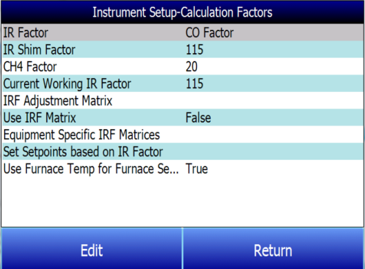
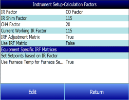
In this menu, there are two factors that will influence the calculation of carbon: IR Shim Factor and CH4 Factor. Each of these factors is incorporated in the equation used to calculate %C; they are described in further detail below. The calculation factors should be changed only after determining that additional adjustments are required based on the specific conditions and equipment at each facility. Neither of them should be modified without significant testing or consultation from Super Systems, Inc.
IR Factor
This setting determines which of two parameters is incorporated in the %C calculation: CO Factor or Process Factor (PF).
IR Shim Factor
Changing the IR Shim Factor is a way of modifying the computed percent carbon. The nominal value is 180. There is an inverse relationship between the IR Shim Factor and computed percent carbon. To increase the computed percent carbon, this number should be lowered, and to decrease the computed percent carbon it should be increased.
CH4 Factor
This factor increases or decreases the significance of CH4 in the calculation of carbon. CH4 does not have a significant impact on the computed percent carbon, so it has a minor role in the equation. If the measured gas has over 5% CH4, its role in the equation may become greater than it should be. In these cases the CH4 factor should be reduced. In cases where the CH4 is present in excess of 7 or 8%, this factor can be reduced to zero.
Current Working IR Factor
This field shows the current IR Shim Factor adjustment value. It is not directly modifiable.
|
Three Methods of %Carbon Calculation
The MGA 6010 is able to calculate %Carbon using one of three methods: Default Settings, IRF Matrix, or Equipment-Specific IRF Matrices.
|
IRF Adjustment Matrix
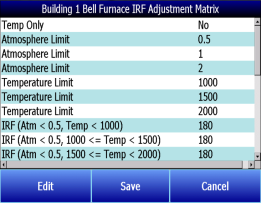
The IRF Adjustment Matrix, sometimes referred to simply as the IRF Matrix, is used to set conditions under which the IR Shim Factor will be changed. Using the IRF Matrix, a total of 16 different IR Shim Factors can be configured if both temperature and atmosphere are considered; a total of 4 different IR Shim Factors can be configured if only temperature is considered. NOTE: Use IRF Matrix must be set to “True” for this function to be used.
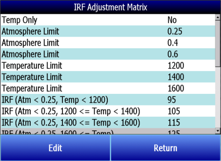
The following steps describe how to configure the IRF Matrix.
-
To begin, decide whether both atmosphere and temperature should be considered in setting the IR Shim Factor, or only temperature.
-
If both atmosphere and temperature apply, set Temp Only to “No” (and then go to step 2 below).
-
If only temperature applies, set Temp Only to “Yes” (and then go to step 3 below).
-
Configure up to 3 atmosphere limits. Each atmosphere limit marks a boundary line within the matrix. Atmosphere values above and below each limit will be evaluated in determining the IR Shim Factor.
For example, if the atmosphere limits are 0.25, 0.4, and 0.6, the following ranges will be evaluated in helping to determine the IR Shim Factor:
-
Less than 0.25 (Atm < 0.25)
-
0.25 – 0.39 (0.25 <= Atm < 0.4)
-
0.4 – 0.59 (0.4 <= Atm < 0.6)
-
0.6 and higher (0.6 <= Atm)
-
Configure up to 3 temperature limits. Each temperature limit marks a boundary line within the matrix. Temperature values above and below each limit will be evaluated in determining the IR Shim Factor.
For example, if the temperature limits are 1200, 1400, and 1600, the following ranges will be evaluated in helping to determine the IR Shim Factor:
-
Less than 1200 (Temp < 1200)
-
1200 - 1399 (1200 <= Temp < 1400)
-
1400 - 1599 (1400 <= Temp < 1600)
-
1600 and higher (1600 <= Temp)
-
Now, enter an IR Shim Factor for each set of ranges. Do this by tapping on a set of ranges and then tapping “Edit”. A numeric entry screen will appear, allowing you to enter a value for the IR Shim Factor.
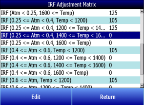
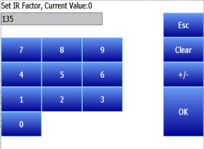
Once IR Shim Factor values have been entered for each set of ranges, the IRF Matrix is configured. The IRF Shim Factor will be set to the configured value for a set of ranges when the atmosphere and temperature (or temperature only, if configured that way) are within those respective ranges. For example, if the atmosphere is 0.3% and the temperature is 1230°, and the IRF for range set
(0.25 <= Atm < 0.4, 1200 <= Temp < 1400) is 125, the MGA 6010 will set the current IR Shim Factor to 125.
Click Return to return to the Calculation Factors screen.
Use IRF Matrix
This setting determines whether or not the IRF Adjustment Matrix is used to set the IR Shim Factor. There are two possible settings: False (default) and True. If Use IRF Matrix is set to False, the IRF Adjustment Matrix will not be used (and Default Settings will be applied). If Use IRF Matrix is set to True, the IRF Adjustment Matrix will be applied to the IR Shim Factor.
Equipment Specific IRF Matrices
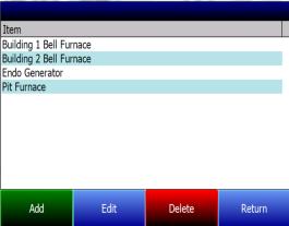
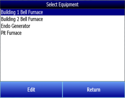
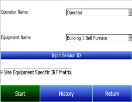
The MGA 6010 can be set up to use different IRF Adjustment Matrices based on the specific equipment whose gas composition is being analyzed. To use this feature, follow the steps below. NOTE: This procedure requires administrator access (default login: ‘2’).
|
|
|
|
|
|
|
|
|
|
|
When ready to start a Session for this piece of equipment:
|
|
|
|
|
Set Setpoints based on IR Factor
The MGA 6010 has the ability to automatically adjust temperature and atmosphere setpoint in an effort to get the Process Variables (PVs) for temperature and atmosphere within a selected range set in the IRF Matrix. This option allows you to select an IRF Matrix range set based on which the MGA 6010 will make adjustments to temperature and atmosphere setpoints. Of course, if the IRF Matrix is configured so that only temperature is used in determining changes to the IR Shim Factor, only temperature will be displayed in the menu for Set Setpoints based on IR Factor, and only the temperature setpoint will be adjusted by the MGA 6010 when this option is used. Note that Use IRF Matrix and Use Furnace Temp for Furnace Setpoint must both be set to “True” for this option to work. In addition, the MGA 6010 must not be configured to communicate with slave instruments; see the IMPORTANT! box below.
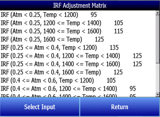
An example of how this option is used can be given as follows. Assume that, in the IRF Matrix, one of the range sets is (0.25 <= Atm < 0.4, Temp < 1200) with a corresponding IR Shim Factor of 135. Because this range set is set up in the IRF Matrix, it will appear as an option in the Set Setpoints based on IR Factor selection list. To apply this range set to the atmosphere and temperature setpoints, the user first taps on the  line in the menu list until that option is highlighted. Next, the user taps on the Select Input button to apply that option.
Once the range set is selected and applied, the MGA 6010 will automatically change the temperature setpoint and (if applicable) atmosphere setpoint. In the Carbon Calculation screen, the Temperature Setpoint and Carbon Setpoint will not be visible or editable while control is based on IR Factor.
|
IMPORTANT!
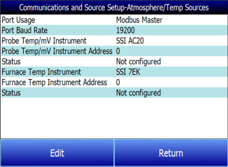
This option will work only when the MGA 6010 is not communicating with any slave instruments. If you attempt to use this option by tapping it and then tapping “Edit” when the MGA 6010 is communicating with a slave instrument, the message “Cannot use this feature with Slave Instrument configured” will be displayed. To disable slave instruments, open the Communications and Source Setup → Atmosphere/Temp Sources menu; then set both the Probe Temp/mV Instrument Address and Furnace Temp Instrument Address to “0”.
|
|
Use Furnace Temp for Furnace Setpoint
When this option is set to “True”, the MGA 6010 will use the furnace temperature as the value used to select an IR Shim Factor. When this option is set to “False”, the MGA 6010 will use the temperature setpoint as the value used to select the IR Shim Factor.
